-
 Thomas Lancaster
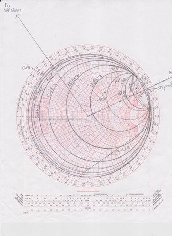
0I was plotting constant-gain circles on the Smith chart the other day for a potentially unstable RF transistor.
Thomas Lancaster
0I was plotting constant-gain circles on the Smith chart the other day for a potentially unstable RF transistor.
I recently read on-line at the link below, that for a potentially unstable transistor the maximum gain that can achieved is the MSG or maximum stable gain. MSG is simply the ratio of the magnitude of S21 over the magnitude of S12.
For my transistor, the MSG in absolute gain 162.5 or 22.1dB as shown on the attached Smith chart.
The on-line article also said that "one should never try to tease more gain from the transistor than the MSG". I have the output stability circle plotted and the unstable region marked as UR on the Smith chart. Notice that some of the 22.1dB constant-gain circle is located pretty far away and outside of the output stability circle's unstable region.
For the heck of it, I plotted gain circles all the way up to the ludicrous values of 50 and 100dB to see what would happen. The 29dB gain circle is dangerously close to but still outside the output stability circle's unstable region.
Only when I jumped to 50 and 100dB did the gain circles just align with the output stability circle. Apparently, gain seems to be infinite with respect to a potentially unstable transistor.
I know that for an unconditionally stable transistor the maximum gain that can be had is the Maximum Available Gain or MAG. In my book, 'RF Circuit Design' by Chris Bowick, Bowick discusses Maximum Available Gain but not Maximum Stable Gain.
When I Plot the constant-gain circles for an unconditionally stable transistor, I found that as the gain is increased, the radius of the circle decreases. When MAG is achieved, the circle becomes a single point on the Smith chart and the equation for the radius of the constant-gain circle becomes undefined. This isn't the case for a potentially unstable transistor. At MSG, the constant-gain circle seems to reach its' smallest radius at 22.1dB(MSG) then increases slightly at 26dB, a little more at 29dB, quite a bit more at 50dB and stays at that size through the ridiculous 100dB gain value.
What is it about MSG that makes it the final word on stable gain when, I'll say, the 23 or even the 26dB gain circle, or at least part of it, seems safely out of the output stability circle's unstable region and seems like there would still be some safe terminating impedances, although not many, available, right?
So is the maximum gain that can be had from a potentially unstable transistor simply at the point where the constant-gain circle reaches its' smallest radius, at MSG = 22.1dB for my transistor, even though the 23,26 and 29dB gain circles still have a portion of their locus outside the output stability circle?
In case you guys are wondering, I want to build a small signal RF amplifier to increase the very weak weather band signal on 162.400MHz and 162.550MHz in my area.
https://www.microwaves101.com/encyclopedias/stability-factorAttachment 001
(175K)
001
(175K)
-
 UnknownEditor
5I have read at least one published paper on positive feedback in the second stage of an LNA. Not sure if this is the article, I don't have ieeexoplore access, but the title sounds useful...
UnknownEditor
5I have read at least one published paper on positive feedback in the second stage of an LNA. Not sure if this is the article, I don't have ieeexoplore access, but the title sounds useful...
https://ieeexplore.ieee.org/document/5161354
I used the technique and convinced myself I could get one dB more gain beyond MSG. I left the company before the chips came out so I never saw the data...
Thanks for the design notes!
Steve


Welcome!
Join the international conversation on a broad range of microwave and RF topics. Learn about the latest developments in our industry, post questions for your peers to answer, and weigh in with some answers if you can!
Categories
- About Our Site
- Antennas
- Applications
- Biological Effects and Applications
- Calculators
- Communications
- Computer Aided Design
- EDA Software
- Emerging Applications and Technology
- Employment
- Field Theory
- Filters and Passives
- General Questions
- High Power
- History
- MMIC and RFIC
- Packaging and Materials
- Radar
- Sources and Receivers
- Test and Measurement
More Discussions
- Terms of Service
- Useful Hints and Tips
- Sign In
- © 2026 Microwaves 101 Discussion Board