-
 Tom
0I've come across something that I cannot find an explanation for although I have a theory. I am currently working on a coax design with a solid PTFE dielectric but using a NbTi wire (unplated) for the conductor. Through all of my calculations, I should be seeing 49.8 ohms. It's seems very basic, wire od, PTFE ID etc. However, when measuring the coax on a real time TDR, it is telling me it is 55 ohms. I've looked at it every which way I can think of and I'm clueless on why this is happening. PTFE is pure, and is properly cured. Could the resistance of the NbTi wire be causing issues with my TDR and artificially showing me an incorrect impedance? All other standard coax tested on the equipment tests the way it should. Thanks for any insight!
Tom
0I've come across something that I cannot find an explanation for although I have a theory. I am currently working on a coax design with a solid PTFE dielectric but using a NbTi wire (unplated) for the conductor. Through all of my calculations, I should be seeing 49.8 ohms. It's seems very basic, wire od, PTFE ID etc. However, when measuring the coax on a real time TDR, it is telling me it is 55 ohms. I've looked at it every which way I can think of and I'm clueless on why this is happening. PTFE is pure, and is properly cured. Could the resistance of the NbTi wire be causing issues with my TDR and artificially showing me an incorrect impedance? All other standard coax tested on the equipment tests the way it should. Thanks for any insight! -
 madengr
1Yes, though Z0=sqrt( (R+jwL)/(G+jwC) ) so a high R will boost the impedance; it’s not artificial. You may have to increase C to compensate. Though I would expect R to be very frequency dependent. Can you sweep it on a VNA, and see what happens at very low frequency such as 300 kHz? You may see a spike in Z0 at very low frequency, which will be exasperated by the R since you are getting sort of a divide by zero.
madengr
1Yes, though Z0=sqrt( (R+jwL)/(G+jwC) ) so a high R will boost the impedance; it’s not artificial. You may have to increase C to compensate. Though I would expect R to be very frequency dependent. Can you sweep it on a VNA, and see what happens at very low frequency such as 300 kHz? You may see a spike in Z0 at very low frequency, which will be exasperated by the R since you are getting sort of a divide by zero. -
 Desert Sage
0Please provide dimensional information. Is relative mu (permeability) of NbTi equal to one? A non unity value would increase impedance. Here mu_r=1.22 would give the result you are seeing.
Desert Sage
0Please provide dimensional information. Is relative mu (permeability) of NbTi equal to one? A non unity value would increase impedance. Here mu_r=1.22 would give the result you are seeing. -
 UnknownEditor
5At some point I would like to capture the ipedance formula that takes into account mu... let me know where there is a good explanation of that.
UnknownEditor
5At some point I would like to capture the ipedance formula that takes into account mu... let me know where there is a good explanation of that.
The microwave office TXLine calculator does show some effect on Z0 when resistance increased, but not enough to explain a 10% shift.
Steve -
Desert Sage
0Z= Zo x sqrt(mu_r/epsilon_r). Skin depth also decreases with increasing mu_r which in turn increases resistivity (rho= L/A and A decreases with mu_r).
-
UnknownEditor
5Not sure I understand where this comes from
Z= Zo x sqrt(mu_r/epsilon_r)
But I'll try to give it some more thought!
Thanks
Steve -
 CMoncsko
1Now seems like a good time to point out that Electroless Nickel (such as in ENIG finishes) is not pure Ni but instead contains "high phosphorus content" typically around 10% P, this effectively makes the Electroless Nickel alloy non-magnetic with a relative permeability mu_r near 1. This is a common electrical simulation mistake where designers might assume electroless nickel has the same properties as pure nickel with a mu_r in the many hundreds.
CMoncsko
1Now seems like a good time to point out that Electroless Nickel (such as in ENIG finishes) is not pure Ni but instead contains "high phosphorus content" typically around 10% P, this effectively makes the Electroless Nickel alloy non-magnetic with a relative permeability mu_r near 1. This is a common electrical simulation mistake where designers might assume electroless nickel has the same properties as pure nickel with a mu_r in the many hundreds.
Another side note, the bulk conductivity is also much worse than pure nickel...
I personally use mu_r of 3, and a resistivity of 60 uOhm-cm. -
 Dillan
0Late to the topic but a good source for this is Pozar 4th Ed. Eq. 2.32.
Dillan
0Late to the topic but a good source for this is Pozar 4th Ed. Eq. 2.32.
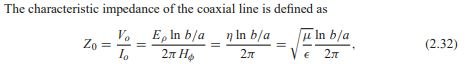
In regards to Z= Zo x sqrt(mu_r/epsilon_r), I don't think so? Especially since the question regarded additional R (hence the conductors mu) but impedance formula uses medium mu. For what it's worth, in above, sqrt(mu/epsilon) = sqrt(mu_0 * mu_r/(espilon_0 * epsilon_r). Generally for coax impedance equations you see mu_r is assumed unity and the free space constants are evaluated out, so only sqrt(epsilon_r) is left in the denominator as a variable. So, if the mu_r of the medium happens to be non unity, the impedance should change by a factor of sqrt(mu_r).
Now for where conductor mu plays a role, of course Z0=sqrt( (R+jwL)/(G+jwC) )
For coax:
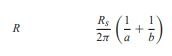
Where:
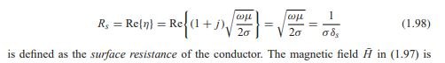
and finally we see conductor mu in skin depth:
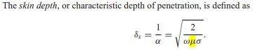
-
madengr
1
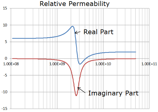
Nickle naturally falls to ur=1 by 10 GHz, and is under ur=10 between 1 and 10 GHz; i.e. ur is very frequency dependent.
I've directly compared bare copper vs ENIG on the same coupon to 60 GHz and seen a good amount of dispersion between the two (of course the thin gold would cause that too), so I'm not entirely sold on ENIG as being harmless. I always use immersion silver, but that just means you need to store the bare boards properly to prevent oxidation prior to soldering. -
CMoncsko
1I didn't know about the heavy frequency dependence, thanks for that! I agree that ImAg is definitely the best passivation for loss, but HASL is a close second (if you can put up with the non-planarity of the pads).
I totally agree that ENIG is not harmless. If the ur is ~1 at higher frequencies, I wonder if it comes down to the bulk conductivity of Ni not being great.
I once found this (single point experimental) data on the permeability of eNi which, looking back on it, supports your assertion of negligible permeability >10GHz
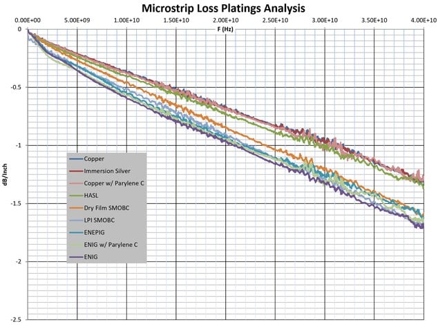
I've also attached an experiment I did with multiple platings on the same board geometry as a passivation loss comparison out to 40GHz. It's obvious that anything with nickel in it is worse. Also note how the loss slope of nickel platings is really steep until ~2GHz and then straightens out. Another piece of evidence of the 2GHz inflection of nickel's permeability!Attachments Electroless Nickel Permeability
(31K)
Electroless Nickel Permeability
(31K)
 Microstrip Loss by Plating
(448K)
Microstrip Loss by Plating
(448K)
-
madengr
1
Awesome plots! On the microstrip, notice the ENIG slopes are not linear until 5 GHz. Pretty sure that's the frequency dependent permeability. The permeability drops quite sharply in UHF, but the effect would be hard to see in thin plating.
I had read a paper from the 40's where they measured Nickle coaxial lines, generating a nice curve of permeability vs frequency through 10 GHz. I'd like to repeat the experiment, comparing two Maury airlines, but I need to fine a used airline I can effectively trash by Nickle plating it.
FWIW there is a company making an RF friendly paraleyne; have not tried it.
https://www.imperial.ac.uk/media/imperial-college/faculty-of-engineering/electrical-and-electronic-engineering/public/optical-and-semiconductor-devices/pubs/2008_06_PIERSO.pdf
https://iopscience.iop.org/article/10.1088/0370-1301/62/6/305/pdf


Welcome!
Join the international conversation on a broad range of microwave and RF topics. Learn about the latest developments in our industry, post questions for your peers to answer, and weigh in with some answers if you can!
Categories
- About Our Site
- Antennas
- Applications
- Biological Effects and Applications
- Calculators
- Communications
- Computer Aided Design
- EDA Software
- Emerging Applications and Technology
- Employment
- Field Theory
- Filters and Passives
- General Questions
- High Power
- History
- MMIC and RFIC
- Packaging and Materials
- Radar
- Sources and Receivers
- Test and Measurement
More Discussions
- Terms of Service
- Useful Hints and Tips
- Sign In
- © 2026 Microwaves 101 Discussion Board