-
 Ronan
0Greetings!
Ronan
0Greetings!
I am hoping someone can point me in the right direction -- I am an amateur radio operator/builder attempting to build and test a dual rhombic antenna, per the author's plan in August 1977 QST article by W8DMR. See figure 4 pg. 26. The antenna was designed for 435-870 MHz, though my primary goal is not so much to include broadcast TV as the author has designed it, but to realize high gain and directivity, on 70cm/440 MHz ham band.
I'd like to run a low-loss 50 ohm coax to this antenna -- as a starting point (guesstimate) I think I am looking at two rhombics in parallel, I'll assume has a Z of 300 ohms. So to start, I have a 1:6 mismatch from my feed line to the Rhombic.
I originally thought I'd make a balun following Ruthroff, Sevick, and others; however I am not so confident about this as most of the balun designs I've looked at are designed for HF and other lower frequencies.
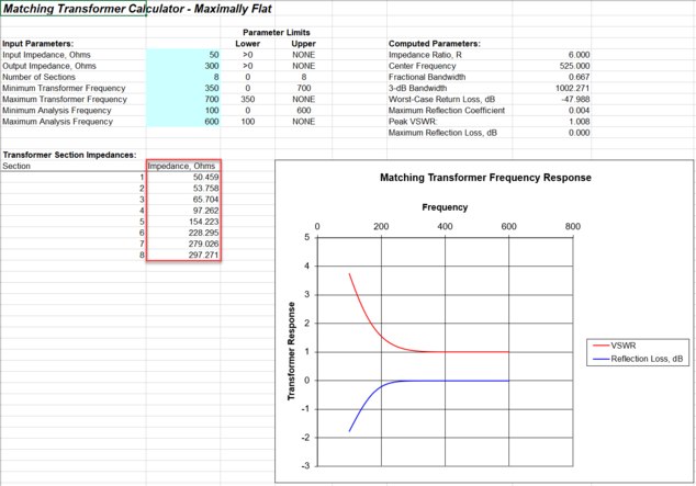
Then, I ran into the wonderful "Maximally-Flat Impedance Transformers" article and spreadsheet here in Microwaves101.com ! See the attached image -- with an 8-section transformer, I see a very pleasing impedance transformation however, how can this be built? Does the Maximally Flat design assume each section of transmission line has the same characteristic impedance as is computed by this spreadsheet?
I though of using an application such as the excellent SimSmith once I had an initial sweep completed with my DG8SAQ VNWA, however, I am not yet certain the VNWA will be accurate with such a wide mismatch (50 into 300 ohms nominally).
Would I want to consider making such a transformer of sections of microstrip or copper traces, wire, carefully spaced to have the Impedance in the results of the spreadsheet?
And/or would I want to model the sections as equivalent transmission lines (L/C/R), then actually building a network of eight LCR sections to emulate physical transmission line sections?
Sorry in advance, for "101" questions!
Thank you very much,
Ronan / KB6NHQ -
 Justin Magers
0Yes, I think that is correct. Your transformer will be made up of transmission lines with impedances of 50.459, ..., 297.217 ohms. I believe an impedance of 297 ohms might be hard to realize in microstrip or stripline. Maybe it has to be twin line?
Justin Magers
0Yes, I think that is correct. Your transformer will be made up of transmission lines with impedances of 50.459, ..., 297.217 ohms. I believe an impedance of 297 ohms might be hard to realize in microstrip or stripline. Maybe it has to be twin line? -
 UnknownEditor
5I am not an antenna designer.... but isn't part of antenna design creating some type of match closer to 50 ohms internal to the antenna? Or maybe just accepting that 3:1 or 4:1 mismatch is good enough?
UnknownEditor
5I am not an antenna designer.... but isn't part of antenna design creating some type of match closer to 50 ohms internal to the antenna? Or maybe just accepting that 3:1 or 4:1 mismatch is good enough?
I agree there that trying to realize 300 ohm in anything but twin lead. Then how will you get twin lead at all the various impedances indicated by the max flat transformer? Eight sections is going to be very long at this frequency band.
How about using a simple "twelfth-wave" transformer?
https://www.microwaves101.com/encyclopedias/twelfth-wave-transformer
Best of luck in any case, and thanks for engaging here!
Steve


Welcome!
Join the international conversation on a broad range of microwave and RF topics. Learn about the latest developments in our industry, post questions for your peers to answer, and weigh in with some answers if you can!
Categories
- About Our Site
- Antennas
- Applications
- Biological Effects and Applications
- Calculators
- Communications
- Computer Aided Design
- EDA Software
- Emerging Applications and Technology
- Employment
- Field Theory
- Filters and Passives
- General Questions
- High Power
- History
- MMIC and RFIC
- Packaging and Materials
- Radar
- Sources and Receivers
- Test and Measurement
More Discussions
- Terms of Service
- Useful Hints and Tips
- Sign In
- © 2026 Microwaves 101 Discussion Board